Rigid locking is used in the tensile direction if spring-back is not desired, e.g. for safety reasons. Rigid locking in the compression direction is recommended if light applications are loaded with very high forces after locking that do not permit any compression.
| Type | HY1 | HY3 | HY4 | HY6 | VOB18-1 |
|---|---|---|---|---|---|
| Valve actuation | On the piston rod side | On the tube side | |||
| Tube | Diameter 22 mm | Diameter 28 mm | Diameter 28 mm | Diameter 28 mm | Diameter 28 mm |
| Locking in the extension direction: rigid up to | max. 3,500 N | max. 7,000 N | 4.8 x F1 max. 7,000 N | 1.6 x F1 max. 1,200 | 1.5 x F1 |
| Locking in the compression direction: rigid up to | 3.6 x F1 max. 6,500 N | 5.8 x F1 max. 10,000 N | max. 10,000 N | max. 1,200 N | max. 3,000 N |
| Characteristics | Max. locking in the tensile direction for small tube diameter | Max. locking in the tensile direction | Max. locking in the compression direction | Particularly large strokes with low extension forces | Particularly short design with medium strokes |
These two types differ only in the diameter of the pressure tube. Due to the arrangement of the oil chamber, the locking in the extension direction is rigid up to the mechanical load limit, regardless of the filling force. In the compression direction, the locking remains rigid until the filling force-dependent limit is fallen below so that the separating piston moves in the direction of the gas chamber.
Due to the relationship of the tube and piston rod cross-section, the limit for the lockable gas spring HY1 is 3.6-times the F1-force and for the lockable gas spring HY3 the limit is 5.8-times the F1-force. This makes applications possible that require a rigid locking against additionally applied loads/weights and where an additional force accumulator is used in addition to the gas spring The limit named for the rigid locking corresponds to the ratio of the load to the dead weight of the application.
| Specification | HY1 | HY3 |
|---|---|---|
| Locking | Rigid in tensile direction | Rigid in tensile direction |
| in compression direction: rigid to/max. Load | 3.6 x F1 / 6,500 N | 5.8 x F1 / 10,000 N |
| in the extension direction: rigid to/max. Load | 3,500 N | 7,000 N |
| Tube diameter | 22 mm | 28 mm |
| Piston rod diameter | 10 mm | 10 mm |
| min. installation length excluding eyelet | 2.6 x stroke + 76 mm | 2.4 x stroke + 76 mm |
| Stroke C | 10 - 300 mm | 10 - 450 mm |
| Extension forces F1 | 80 - 800 N | 80 - 1,000 N |
| Progression (F2/F1) | < 1.6 | < 1.5 |
| Release force | 0.25 x F1 N | 0.25 x F1 N |
| Release travel, short | max. 0.5 mm | max. 0.5 mm |
| Release travel, normal | 2.5 ≤ x ≤ 3.5 mm | 2.5 ≤ x ≤ 3.5 mm |
| Recommend installation position | arbitrary | arbitrary |
| Permissible operating temperature | -20°C to +60°C | -20°C to +60°C |
| Permissible storage temperature | -20°C to +80°C | -20°C to +80°C |
| Possible special functions: | ||
| EasySwitch ES | x | x |
| TimeReset TR | x | |
| OverRide OR | ||
| ComfortReleaseLow CL | x | x |
Due to the arrangement of the oil chamber, the locking in the compression direction is rigid up to the mechanical load limit, regardless of the filling force. In the extension direction, the locking remains rigid until the filling force-dependent limit is fallen below so that the separating piston moves in the direction of the gas chamber. Due to the relationship of the tube and piston rod cross-section, the limit for the lockable gas spring HY4 is 4.8-times the F1-force.
This makes applications possible that require an extremely rigid locking against additionally applied loads/weights in the pressure direction. In the extension direction, the limit already named for the rigid locking corresponds to the ratio of the load to the dead weight of the application.
| Specification | HY4 | |
|---|---|---|
| Locking | rigid in the compressive direction | |
| in the compression direction: rigid to/max. Load | 10,000 N | |
| in the extension direction: rigid to/max. Load | 4.8 x F1 / 7,000 N | |
| Tube diameter | 28 mm | |
| Piston rod diameter | 10 mm | |
| min. installation length excluding eyelet | 2.6 x stroke + 85 mm | |
| Stroke C | 10 - 300 mm | |
| Extension forces F1 | 80 - 1,000 N | |
| Progression (F2/F1) | < 1.6 | |
| Release force | 0.25 x F1 N | |
| Release travel, short | < 0.5 mm | |
| Release travel, normal | 2.5 ≤ x ≤ 3.5 mm | |
| Recommend installation length | Piston rod facing down | |
| Permissible operating temperature | -20°C to +60°C | |
| Permissible storage temperature | -20°C to +80°C | |
| Possible special functions: | ||
| EasySwitch ES | x | |
| TimeReset TR | x | |
| OverRide OR | - | |
| ComfortReleaseLow CL | x | |
Due to the arrangement of the oil chamber, the locking in the compression direction is rigid up to the mechanical load limit, regardless of the filling force. The special two-pipe design ensures a particularly low force increase during long strokes. This makes applications possible that require extremely long strokes with a short design and yet force-independent rigid locking in the compression direction.
| Specification | HY6 | |
|---|---|---|
| Locking | rigid in the compressive direction | |
| in the compression direction: rigid to/max. Load | 1,200 N | |
| in the extension direction: rigid to/max. Load | 1.6 x F1 N / 1,200 N | |
| Tube diameter | 27 mm | |
| Piston rod diameter | 10 mm | |
| min. installation length excluding eyelet | 2 x stroke + 110 mm | |
| Stroke C | 10 - 450 mm | |
| Extension forces F1 | 70 - 400 N | |
| Progression (F2/F1) | < 1.6 | |
| Release force | 0.25 x F1 N | |
| Release travel, short | < 0.5 mm | |
| Release travel, normal | 2.5 ≤ x ≤ 3.5 mm | |
| Recommend installation length | arbitrary | |
| Permissible operating temperature | -10°C to +60°C | |
| Permissible storage temperature | -20°C to +80°C | |
| Possible special functions: | ||
| EasySwitch ES | - | |
| TimeReset TR | - | |
| OverRide OR | x | |
| ComfortReleaseLow CL | x | |
Due to the arrangement of the oil chamber and the valve at the end of the pipe, the locking in the compression direction is rigid up to the mechanical load limit, regardless of the filling force. The special two-pipe design ensures a particularly short design. This makes applications possible that have an extremely narrow installation space and yet require a force-independent rigid locking in the compression direction.
| Specification | VOB 18-1 |
|---|---|
| Locking | rigid in the compressive direction |
| in the compression direction: rigid to/max. Load | 3,000 N |
| in the extension direction: rigid to/max. Load | 1.5 x F1 N |
| Tube diameter | 28 mm |
| Piston rod diameter | 10 mm |
| min. installation length excluding eyelet | 2 x stroke + 90 mm |
| Stroke C | 20 - 300 mm |
| Extension forces F1 | 150 - 1,000 N |
| Progression (F2/F1) | < 1.7 |
| Release force | 0.4 x F1 N |
| Release travel, short | - |
| Release travel, normal | 2.5 ≤ x ≤ 3.5 mm |
| Recommend installation length | Piston rod facing down |
| Permissible operating temperature | -20°C to +60°C |
| Permissible storage temperature | -20°C to +80°C |
The standard program for rigid locking gas springs includes two different types.
| Type | ∅ Tube(mm) | ∅ Piston rod(mm) | Stroke(mm) | Extension force* F1 (N) | Color tube | Color Piston rod | Type of locking |
|---|---|---|---|---|---|---|---|
| HY1 | 22 | 10 | 20 - 250 | 200 - 800 | black | Tenifer | rigid |
| HY3 | 28 | 10 | 20 - 250 | 200 - 1.000 | black | Tenifer | rigid |
* The extension force is selectable in steps of 50 Newton
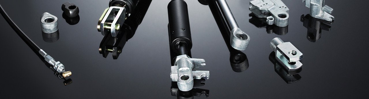
As a system supplier, we offer different end fittings and release systems that are specially tailored to the respective application for our lockable gas springs Varilock. This ensures an optimal function of the lockable gas springs.
![]()
Easily, quickly and conveniently configure your custom lockable gas spring from various versions and connections with the CAD configurator.
Order in our online shop.